Whether you’re a newbie or professional in the world of boating, outboards are one of the terms you’ll likely hear often. An outboard motor is a propulsion system for boats. It’s a crucial part and the most prevalent motorized means of propelling watercraft.
In today’s market, there are many different kinds of outboard engines. Some of the best include Johnson Evinrude, Mercury Marine, and Yamaha Seven Marine. If you’re seeking to buy an outboard motor, it pays to understand the system to know what you’re buying.
In this guide, we’ll provide the diagram of the Johnson outboard parts and discuss the different functions of the components among other information.
Johnson Outboard Parts Diagram
The Johnson outboards are complex and sophisticated engines built to last long with exceptional performance. These systems are different from most others. While they may seem confusing to understand, learning about the component will ease any repair process and reveal how each part work.
The diagram below shows the different components of the Johnson Outboard:
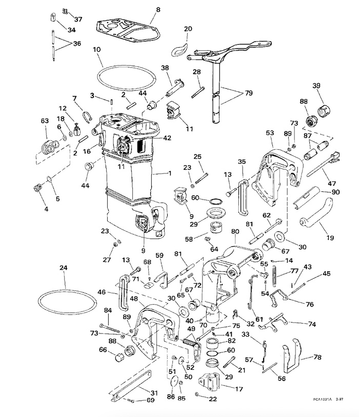
- Exhaust Housing Assy
- Exhaust housing Pin
- Gasket Aligning Roll Pin
- Plug & Nozzle Assy
- O-RING, Overboard indicator
- Washer
- Tie Strap Hose
- Gasket
- Mount
- Seal
- Upper Mount
- Clamp
- Tilt lock Screw
- Lube Fitting
- Screw
- Lower mount Bracket
- Reed Valve
- Carrying Handle
- Steering Arm Seal
- Screw
- Locknut
- Washer
- Exhaust Housing Seal
- Mount Screw
- Lower Mount Screw Nut
- Upper Mount Screw
- Pivot Shaft Seal
- Washer
- Tie Bar
- Spring
- Reverse Lock Spring
- Connector
- Lock Assy
- Shift Rod
- Shift Rod Clip
- Lever & Shaft Assy
- Wiper Nut
- Fitting
- Clip Pin
- Lube Fitting
- Cotter Pin
- Bushing
- Pin
- Lock Assy
- Tilt Pin
- Stern Bracket
- Handle & Screw Assy
- Swivel Plate
Johnson Outboard Motor Ignition Parts Explained
When you’re using a Johnson outboard motor ignition, you’re guaranteed excellent performance coupled with immense durability. Thanks to some crucial components, the outboard motor offer premium services. Such components include the flywheel, the trigger, the stator, the ignition coil, and the power pack.
Let’s discuss the different functions of each component.
Flywheel
Together, the trigger, stator, and flywheel produce the electrical fields needed to charge the system’s energy as well as a reliable indicator of the crankshaft’s location. The moving component of a generator is the flywheel, which has magnets attached to it.
As a result of the magnets rotating past and near the stator, the electricity will have fully built up. Magnetic fields are moved over and across coils to create electricity; in this instance, the coils are situated in the stator.
Stator
The stator is a very simple component with simple work. The stator is immobile and is sitting still. The majority of the coils in the stator’s network produce electricity for the charging system.
The ignition system’s charge coils are separate, independently functioning coils that are part of the stator. The ignition system is powered by the charge coils, enabling proper operation.
Trigger
The trigger assembly detects the crankshaft position and communicates the appropriate time the system should fire. Its function is similar to that of a crank angle sensor in modern cars or a pick-up coil in a distributor.
If it sends the signal to the system at the wrong time, making it misfire, the whole system becomes obsolete.
Generally, the timing of the spark plugs’ ignition will need to change to account for the engine’s mechanical movements at increased RPMs to ensure that the fuel burns at the proper moment.
For this reason, the timing must be advanced or delayed to the proper setting. Because of this, the trigger does move, but the throttle mechanism’s adjustable limiter prevents it from moving further.
Power Packs
The power pack is also known as the switch box, depending on how the ignition is configured. The power pack work continues from where the triggers stop.
The power packs use the charge coils in the stator to draw power from, which they then transfer to the ignition coils. A piece of information from the trigger is used to determine which coil should receive power.
Power packs manage the flow of energy, ensuring that the right cylinders are fired at the appropriate time by the spark plugs. It might seem like the trigger’s job, but the trigger only outputs data to the power pack; it doesn’t deliver power. Because of this, the power pack is more akin to a system controller.
However, the power pack is prone to some problems including no fire or misfiring. If you notice this complication, you should contact a specialist to help with the diagnosis because the troubleshooting process isn’t easy.
Ignition Coils
The ignition coil is another crucial component of the outboard motor ignition. It is responsible for feeding power to the spark plug. For the spark to jump on the spark plug electrode, the ignition coils increase the power sufficiently. A voltage increase to several thousand volts is used to accomplish this.
Normally, the positive lead of the ignition coils is connected to the power packs, which receive power from the grounding of the coils. The power pack can control the timing of the spark as well as generate the spark to kindle the fuel because the coils instantly ignite when the power is applied.


