Marine engines are a critical component of the world’s trade. They help propel humongous ships through the seas without many hurdles. They offer propulsion energy crucial for the vessel to move and run ahead and behind directions at varying speeds.
The Indmar Marine engine is one of the best out there. In this article, we’ll use the diagram of the Indmar marine engine to break down the crucial components so you can better understand how each part functions.
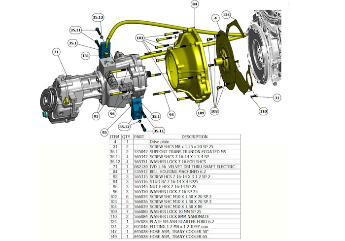
Indmar Marine Engine Parts Diagram
Indmar is a leading company in the industry that provides cutting-edge, inboard power technologies engines that last longer. The Indmar marine engine is available as a two-stroke and four-stroke machine. Still, a large percentage of it is available in four-stroke engines.
Here’s a diagram showing the Indmar marine engine with all the components labeled accordingly:
Indmar Marine Engine Parts Explained
Now that you’re familiar with the components that make up the Indmar marine engine, let’s discuss the function of the crucial elements and how each fits into the big picture.
Cylinder Block
The Cylinder Block is also known as the Entablature. It typically rests on top of the A-frame and comprises different engine components, including jacket cooling water, stuffing boxes, scavenge space, and the cylindrical cavity.
One of the critical parts of your engine is the cylinder block.
It is regarded as the brain and one of the engine’s critical parts. It is made from top-notch materials to fulfill the purposes for which each of its parts was designed. There is no room for cutting corners because it is essential for the engine’s stability, temperature control, and lubrication.
Crankshaft
One of the most crucial parts of the engine is the Crankshaft. This component, along with the connecting rod, transforms the engine pistons’ reciprocating motion into the propeller’s rotational motion.
This torque is turned into axial thrust by the propeller, which propels the ship. The piston, combustion, propeller, and flywheel place various loads on the crankshaft. Therefore, it must be designed to handle these extensive loads.
The crank webs, crank pins, and journals make up the crankshaft. The specific materials used in the shaft vary depending on the application, though it is typically made of alloyed steel. The crankshaft’s characteristics are provided by substances like semiconductor materials, nickel, vanadium, and chromium.
Connecting Rod
The crankshaft and piston are joined by a con-rod, which helps turn the piston’s reciprocating motion into rotation. The piston is connected to the crankshaft by the con-rod, which transmits combustion pressure to the crankshaft.
On one end, the connecting rod is connected to the crankshaft, and on the other, to the crosshead. The crosshead goes up and down with the piston, which causes the connecting rod to move up and down as well. The crank pin and, consequently, the crankshaft are moved in a circular motion by the connecting rod using this motion.
Bedplate
The portion of the engine that holds the engine’s weight at the bottom is called the bedplate. Therefore, it is the component of the machine that is most loaded. For stability, it is attached to chocks and fastened to the ground with holding-down bolts.
The bedplate’s primary duties include:
- Supporting the static load of stationary engine blocks and frames.
- Sustaining the running equipment’s dynamic load.
- Holding the crankshaft firmly in place to provide support.
A Frame
The A-frame resembles the Letter A as its name implies. It’s elected on the bedplate to the bottom and supports the entablature or cylinder block at the top. Its duties include:
- Aiding the cylinder block or tablature.
- Housing the crosshead and its guide.
- Keeping the crankshaft balanced.
- Forming the crankcase space.
The A frame is fastened to the engine, employing tie and fitted bolts. A tie bolt holds the A-frame, bedplate, and entablature, to the vessel instead of fitted bolts, which link the A-frame and the bedplate.
Piston
An essential component of a marine engine’s combustion chamber is the piston. It uses reciprocating motion to transform the force of the gas into mechanical power. Three parts make up the piston arrangement in marine diesel engines: the piston rod, trunk piston, and skirt.
It integrates into the engine cylinder when used with two-stroke or four-stroke engines. It transfers mechanical force to the piston rod or connecting rod, respectively.
Cylinder Cover Or Head
The cylinder head or cover is another crucial component to know. It’s the topmost part of the engine structure. It’s a significant component in controlling airflow in and out of the cylinders and fuel deployment.
It also holds injectors and valves. It comprises different monitoring instruments and mountings, including a fuel injector or valve, indicator valve, cylinder relief valve, starting air valve, and exhaust valve, among others.


